On Hidden Victories: Repairing My Eclipse’s Radio
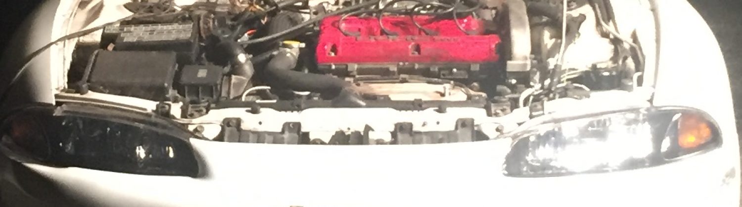
Last weekend, I decided to tackle a project which had been on my mind for a while. My ’98 Eclipse’s radio was having a few issues that I wanted to address.
First, the rotary encoder (or, more simply put, the “knobby thing you adjust the volume with”) was behaving erratically. Sometimes when I’d turn the volume up, it would decide it was actually going to quiet things down for me. Other times, I would try to adjust the volume, only to have it blast like I was at a neighborhood block party (do people have those still?).
Second, the tape player stopped working. Yes, I know. The tape player. “Bernie, who the hell uses tape players anymore? It’s 2019. Time to crawl out from under your rock.” Slow down. I have Bluetooth tapes which I use to sync my iPhone to. Pretty fancy, right?
Unfortunately, I was probably the first person to use that tape player in many years. And I used that player every day. It was like asking someone who hasn’t exercised in 20 years to go run a 10k. As you can imagine, in both scenarios, things break, people cry, feelings get hurt.
For the tape player, this was the rubber drive belt that connected all of the drive wheels which fed the tape. So, when I would try to put a tape in, it would chew on it for a moment and then spit it back out at me.
Before I go any further into the escapade, I need to thank my father for helping me out on this one. I certainly couldn’t have done this alone (turns out removing solder from a board by yourself is pretty tricky). It’s another illustration where I see how important it is to lean on the strengths of others and learn from them when I have a knowledge gap. He’s been doing that for me for years, and that weekend’s project was no exception. So, thanks dad for all of your help! You are much appreciated.
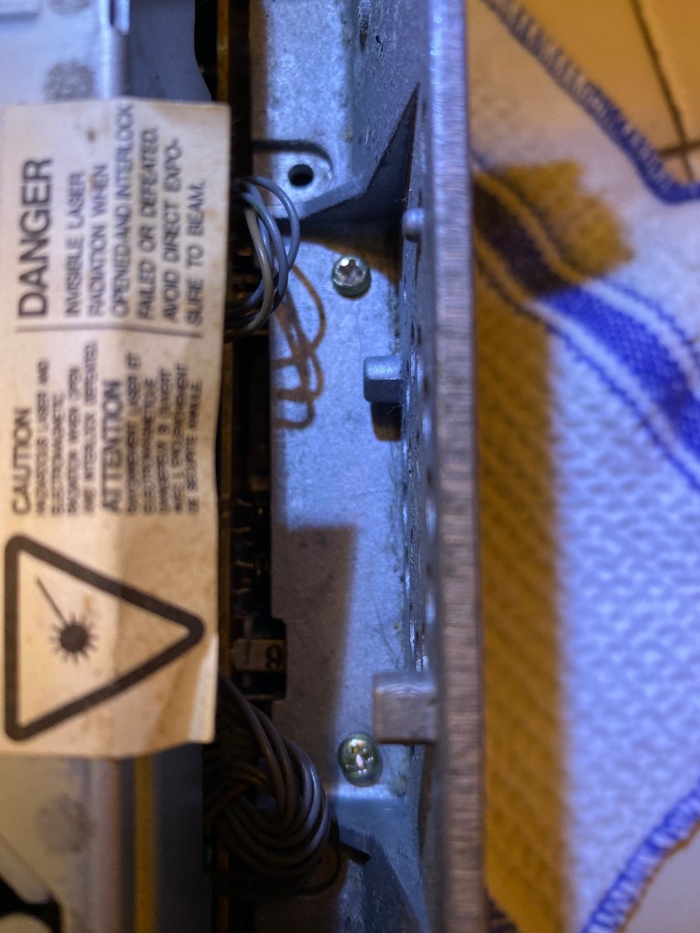
I found a few neat things as I was taking the radio apart. Obviously, all parts usually have a designated part number and such, but I always find that original stickers such as these are like snapshots in time. There’s a certain fascination that comes with uncovering something which makes it feel as though you are the first to see something which hasn’t been touched since it was last used or first created. I did think this was maybe the case until I looked on the bottom of the radio. Someone had written in pencil the pin layout for the plug in the back, indicating they had probably done some kind of repair. This was confirmed by a repair stick posted on the top which said 2001. So, someone else had been in there, but not for a long time.
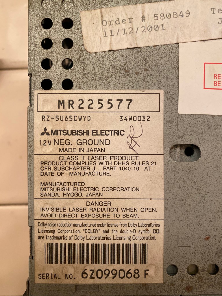
The original Mitsubishi Electric sticker. The “MR” number on the top is Mitsubishi’s part number for the radio. 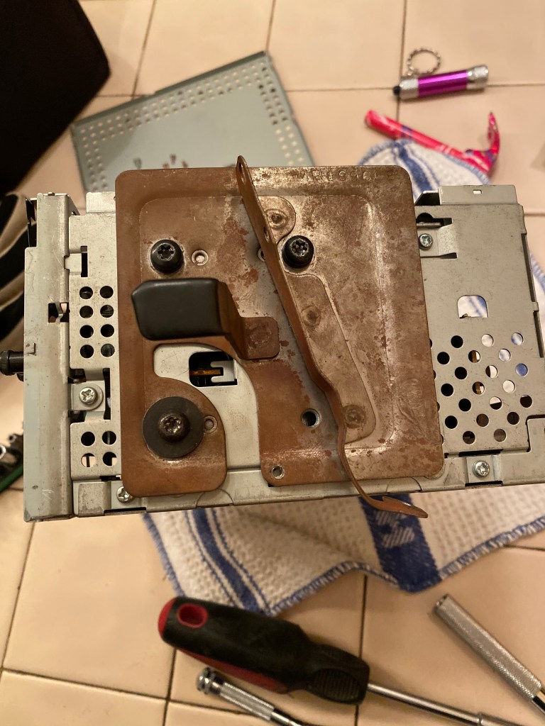
These brackets hold the radio in place in the car. 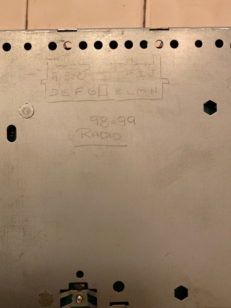
Looks like someone was here before… 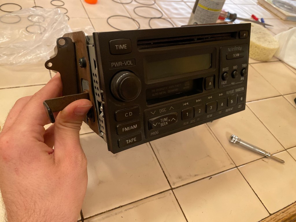
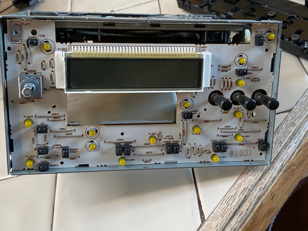
Front face plate of the radio.
Diving in
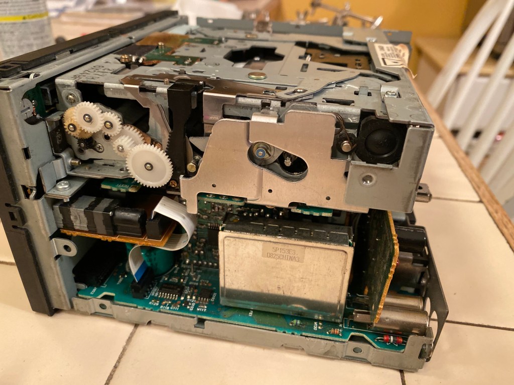
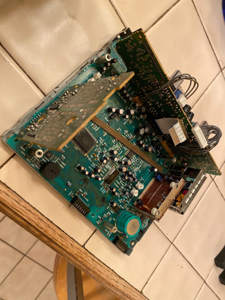
My main concern was taking care of the tape player. Being at the bottom of the radio, I’d have to separate the CD player from the top. If you take a look below, you’ll see the big box on top with the white gears. That’s the CD player. It’s really fascinating to see how it works. Powered by a motor, the large gear on the bottom rotates up a toothed track, causing the CD which is currently inside to rise up on rollers. As it nears the top, a set of levers move to pull the locks out of the way (they are there so that you can’t put another CD in when one is already in there).
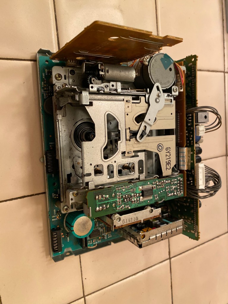
Once the CD player was removed, the tape player became visible. Again, there were quite a few levers that were driven by a motor to either accept and play a tape, or lift it up and out. Take a look at the video below to see it in action.
Once the tape player was out, I could take the new rubber drive belts I purchased and wrap one around the tape drive wheels. This turned out to be the easiest part of the project.
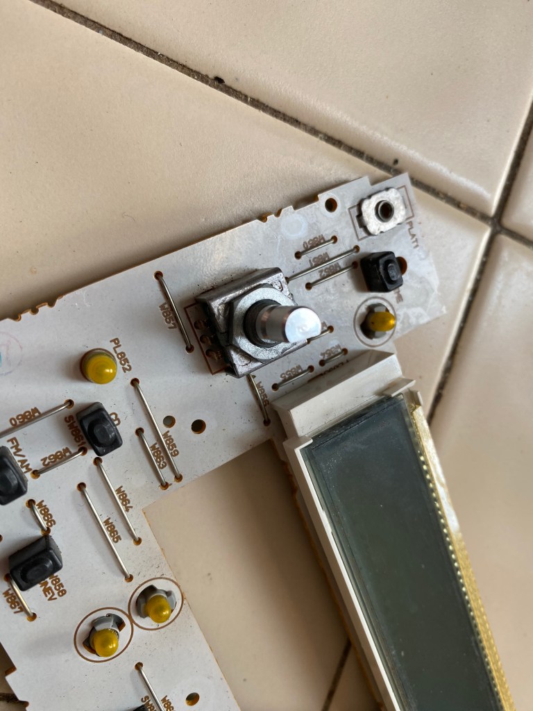
If you look at the picture above, you’ll notice that the encoder has a retaining nut that screws on and a small metal shroud. This shroud was actually soldered to the back of the board to keep everything in place. Since the encoder can be depressed to power the radio up or down, it needs to be sturdy (you don’t want to press it and have it fall off of the circuit board. That would cause a whole host of problems).
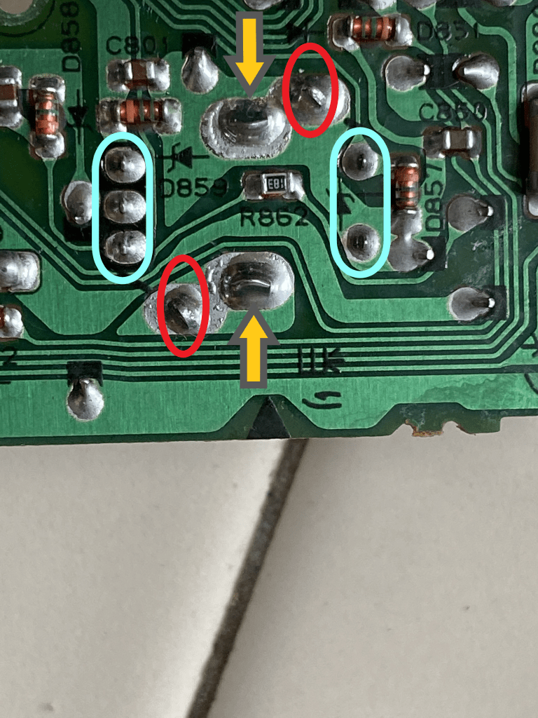
Above, you can see the view of the encoder from the back of the circuit board. The aqua-colored circles show the actual electrical solder points which are part of the circuit; the orange arrows indicate the physical mount points for the encoder; and the red circles point out where the small metal shroud is mounted by its tabs. Those tabs are actually put through slots in the board and then twisted before being soldered for extra support.
In order to remove the encoder, my father decided we should heat up the solder and then use a solder sucker (or desoldering pump) to remove the molten metal. In short, the solder sucker works by quickly vacuuming up the solder.
Doing this alone would have been doable but difficult, so we decided that I would heat up the solder and then my father would quickly vacuum it up with the pump. This worked out quite well and, after desoldering all connections, the encoder was finally free from the board.
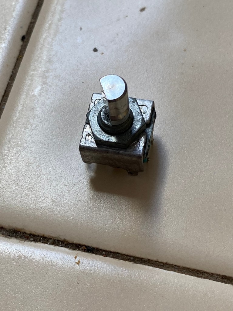
The is the encoder with the shroud still on. 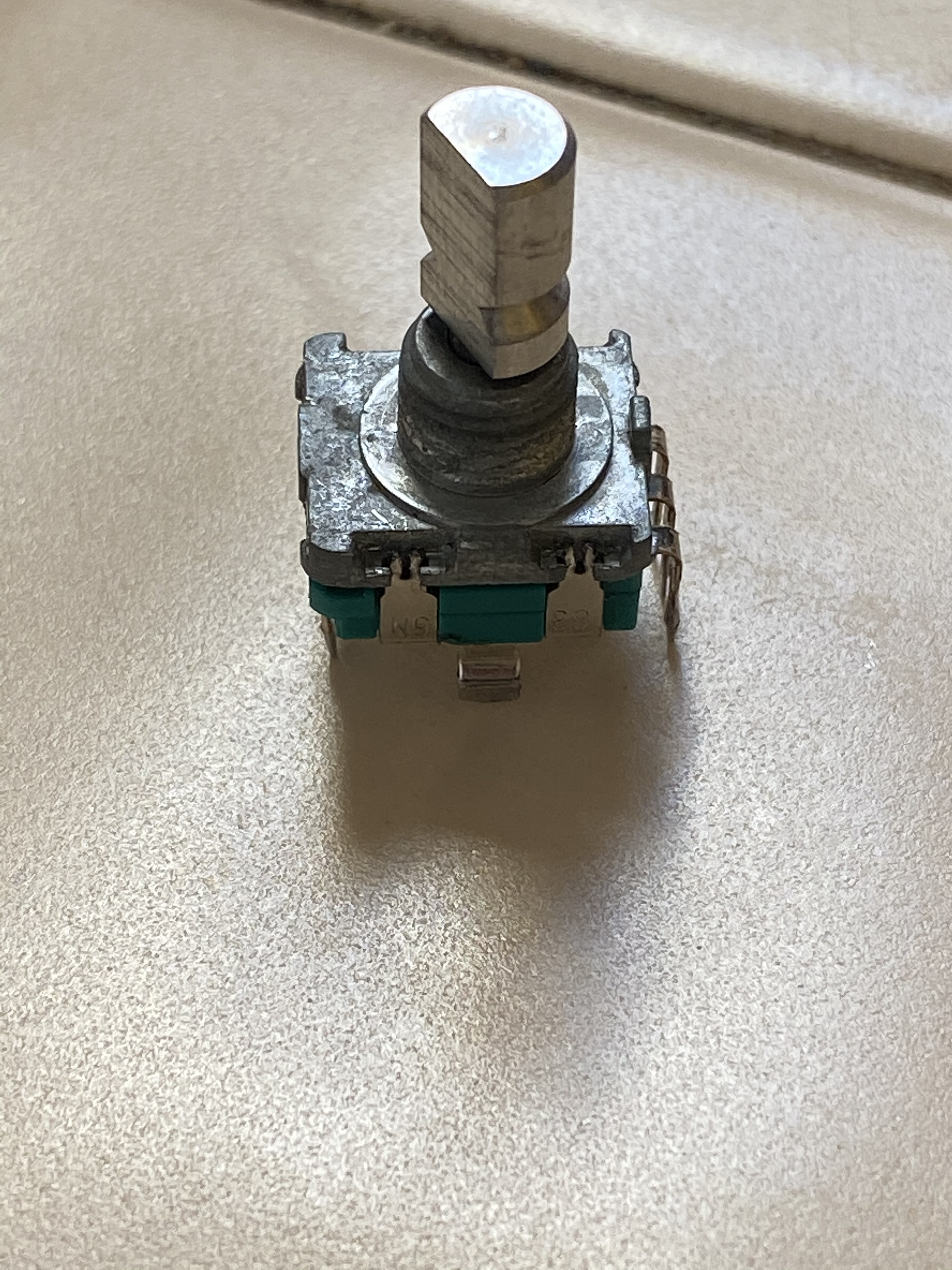
Shroud removed. 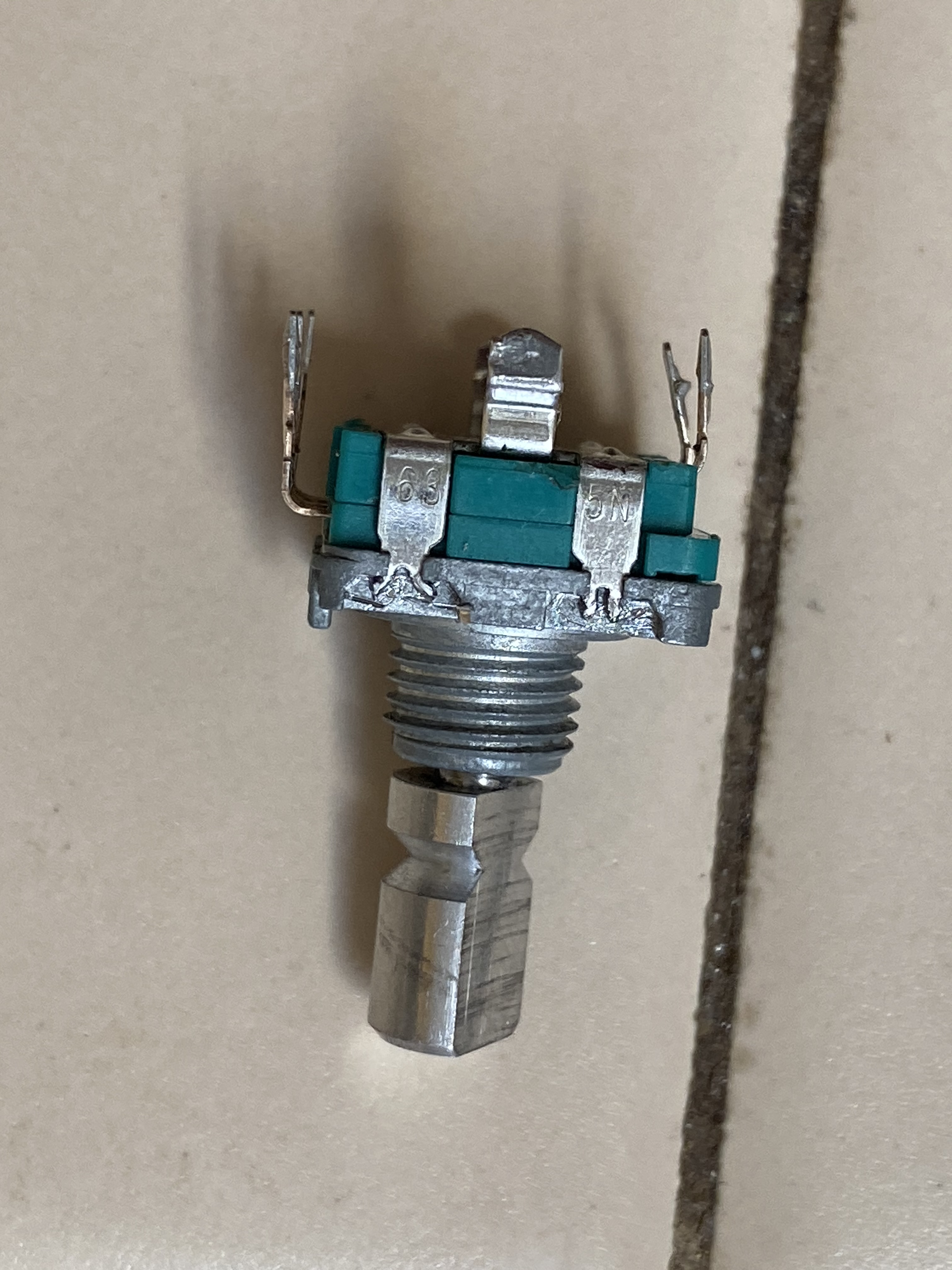
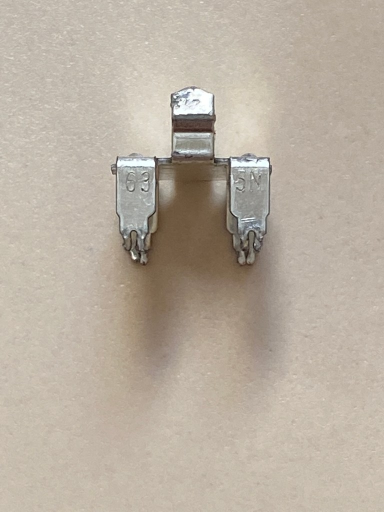
The little tabs that hold the green base on have these little forks which need to be close in order to separate the pieces. You can see the one on the right is closed and the one on the left is open. 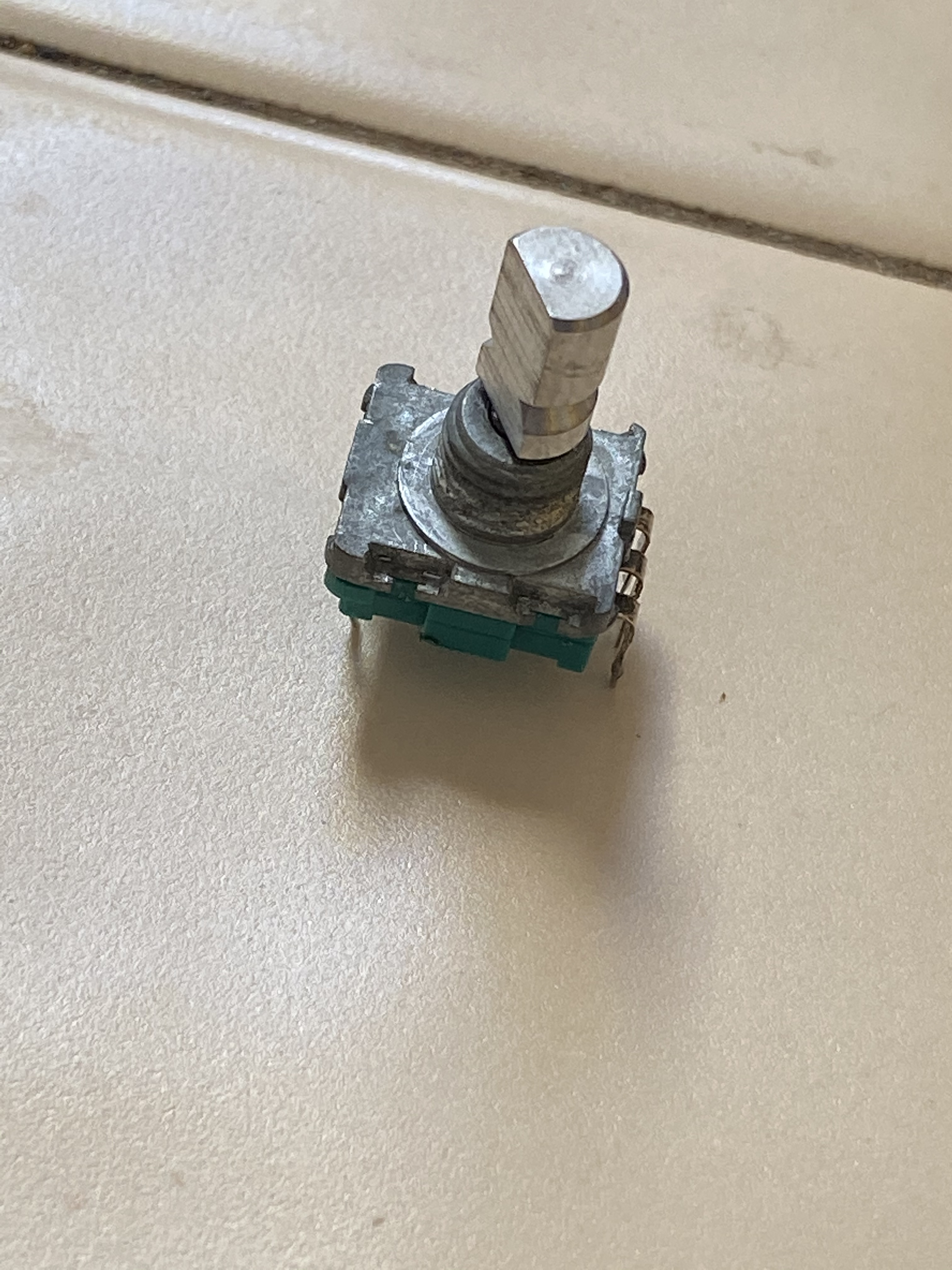
At first, we tried to find a replacement encoder. We figured rather than taking it apart, this might be the easier route to take. Unfortunately, we did not have much luck. There was a number printed on one side of the tabs and the name of the brand on the bottom, but these turned out to lead to dead ends.
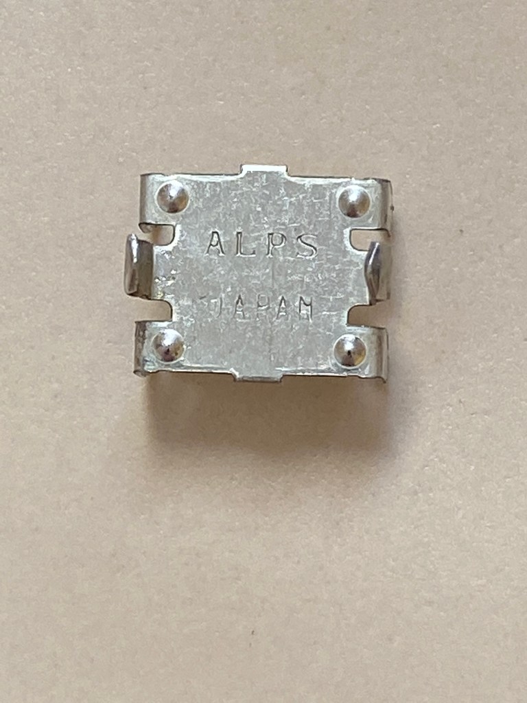
We hoped that “Alps 635N” would be the winning search. Though Alps still exists, the part number appears to be (understandably) outdated. We took a series of measurements with a micrometer, but no current products from any company matched the dimensions.
I was afraid to take the encoder apart because I had no idea what was inside and whether or not I’d be able to get it back together. I did some research and found this video by a guy taking apart an encoder on a Sony stereo. I need to give credit to him for showing me how easy this process actually is and giving me the courage to move forward. Thank you kind stranger!
Armed with this new information, I bent those little forks on the tabs and pulled the encoder apart. Below are some pictures of the inside and descriptions of what they are.
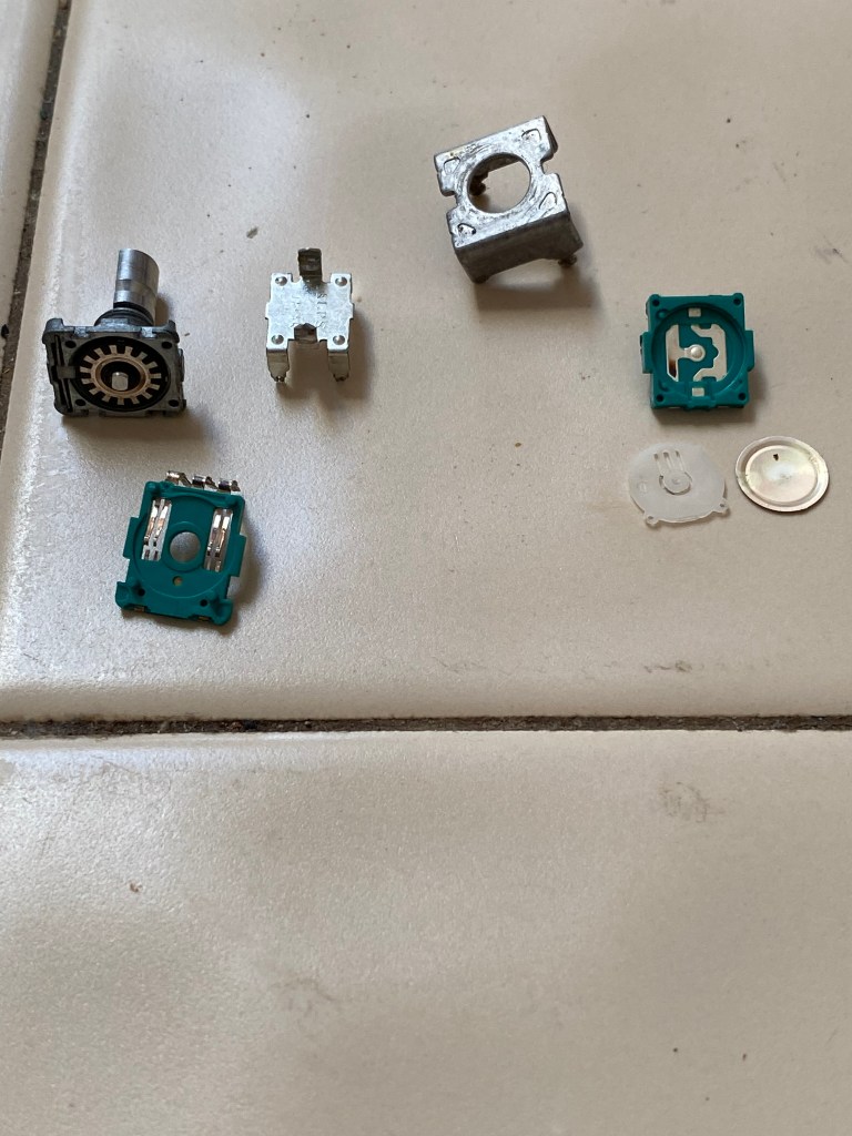
The spread of parts found inside. 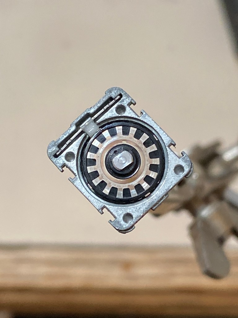
This is the encoder. From what I understand, each time one of those fins passes over the connections below, it sends a stepped pulse of electricity, telling the PC to either increase or decrease the volume. 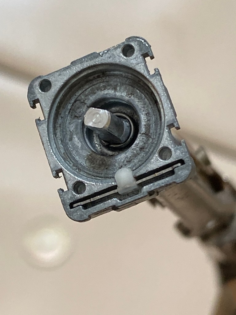
This is the housing with the encoder disc removed. The shaft extends through to rotate it. 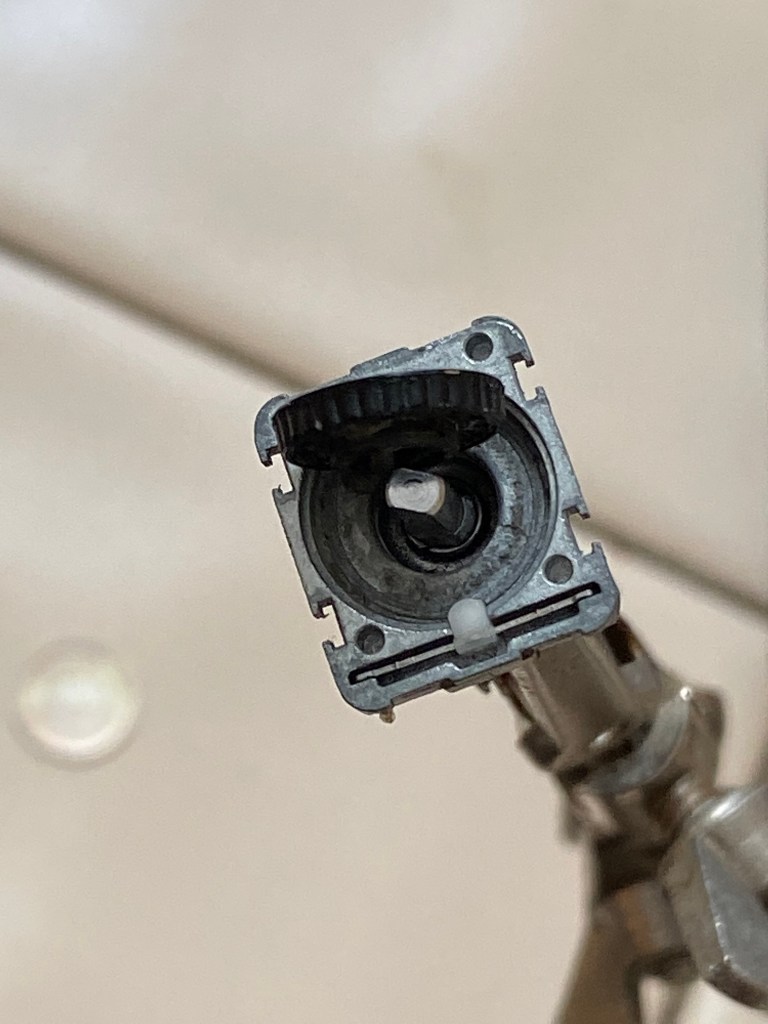
The black part in the image is a side view of the encoder disc. You can see little teeth on it, which explains why you get that clicking sound and feeling as you rotate the knob. If you look at the previous image and this one, you’ll see a small white tab at the bottom of the housing. This is responsible for the clicking. 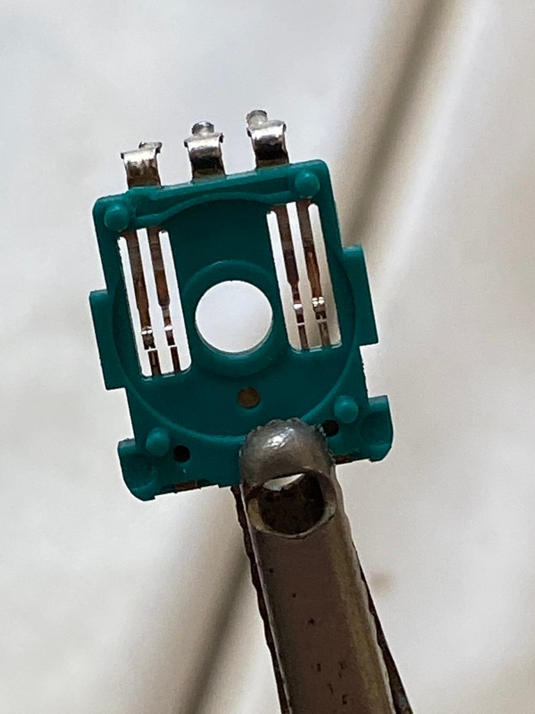
The raised metal strips in the center touch the encoder disc and then transfer the electrical communication through the three soldered tabs to the PC board.
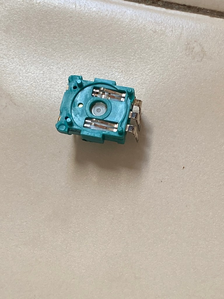
This perspective provides a better view of the way the strips are raised to make contact with the encoder. 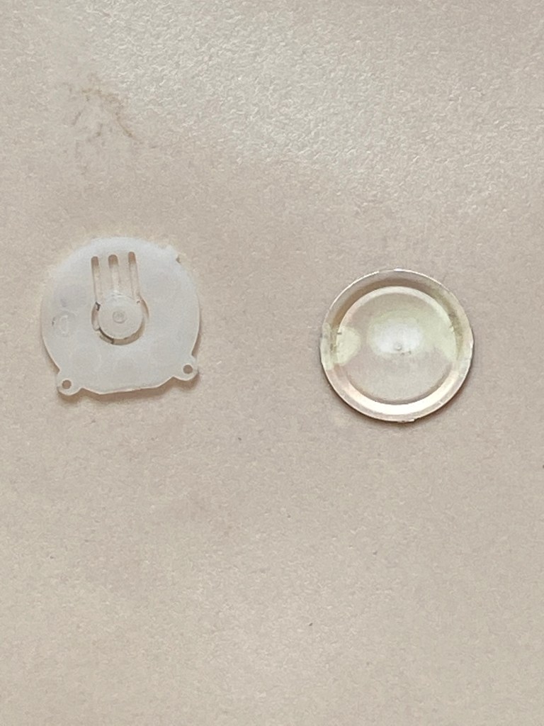
These parts are part of the system used to turn the radio on and off. The white part is flexible in the center, allowing the shaft of the encoder to be depressed, make contact, and rebound. The metal disc is slightly conical. This is what makes the “click” sound when you press the switch. 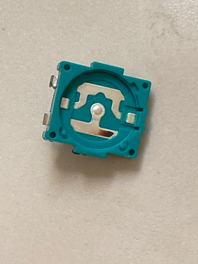
When the metal disc from the previous image is flattened, it makes contact with this part of the encoder, which is connected to the PC board by the other two soldered tabs. The depressed disc touches the center of the piece here, telling the PC to either turn the radio on or off. 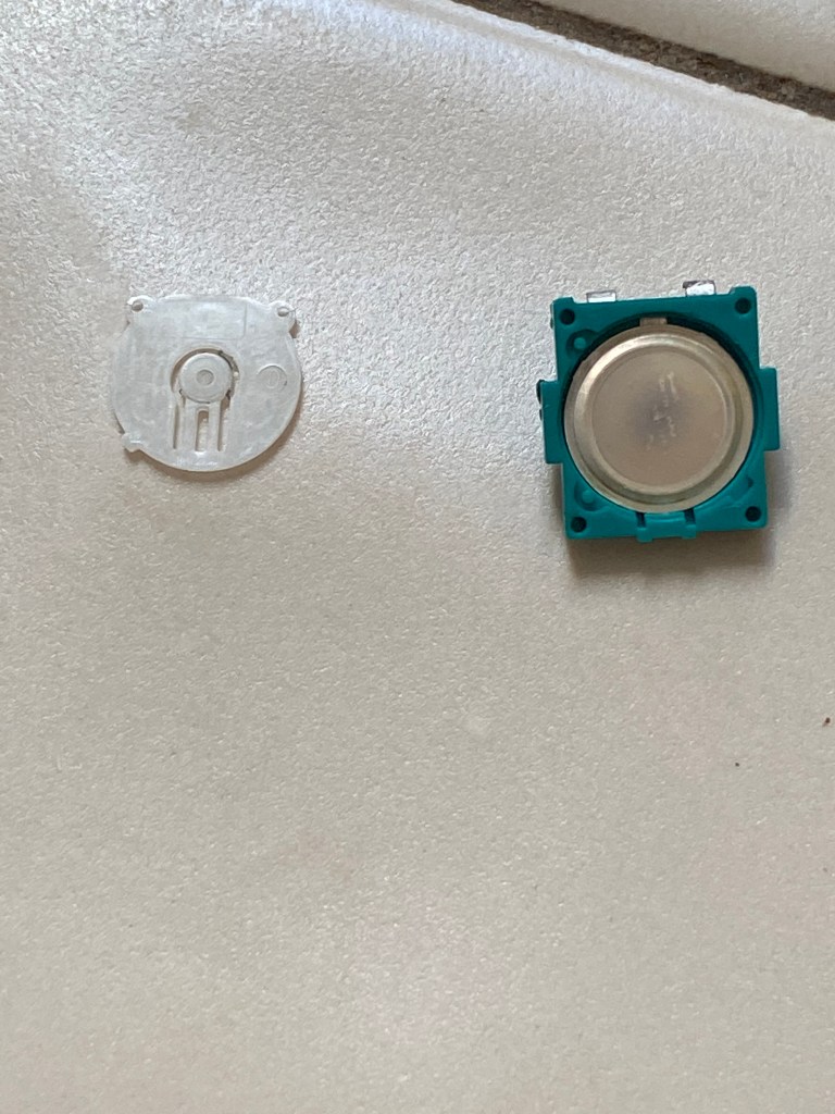
This is how the metal disc fits into the previously shown part… 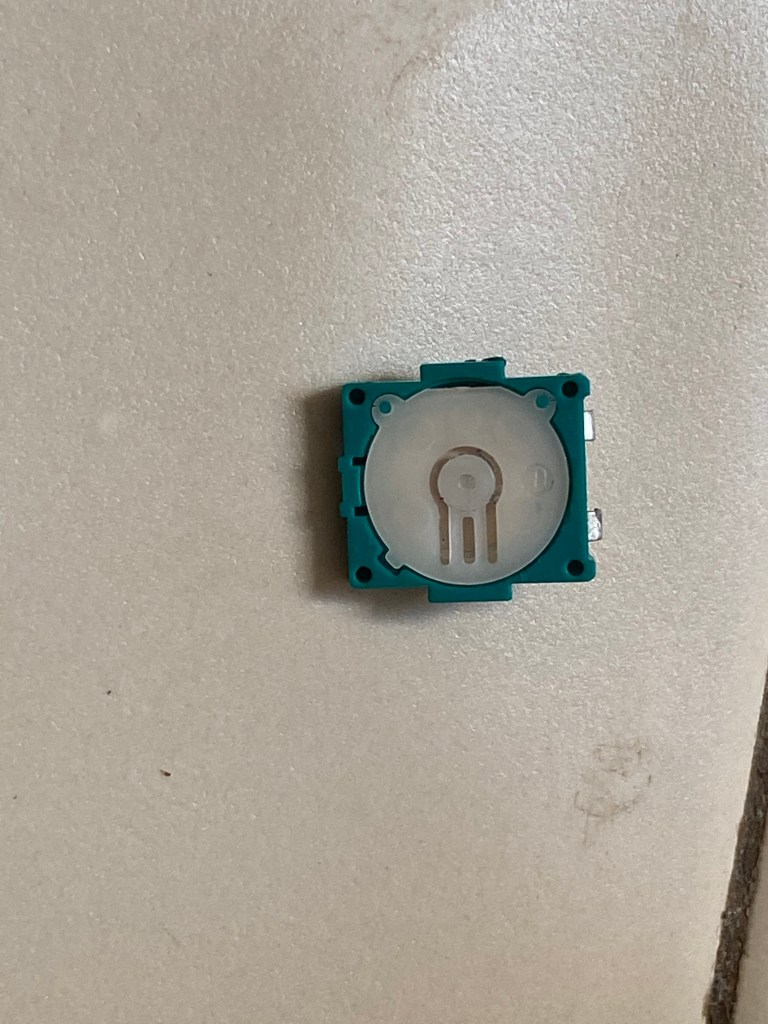
…and then the white disc on top.
Using some denatured alcohol and a cotton swap, I cleaned up any residue that was on the encoder. The constant electrical contact can cause a buildup which blocks or redirects the electrical signal, causing the problems I was experiencing. Once this was complete, I reassembled it, closed the little forks, and placed it back on the board to solder again.
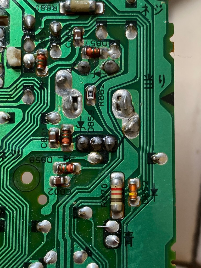
A little side note on something else I enjoyed seeing: since the board was made in Japan, there were small markings written in Japanese. It isn’t anything to special, but I thought it would be interesting to point out.
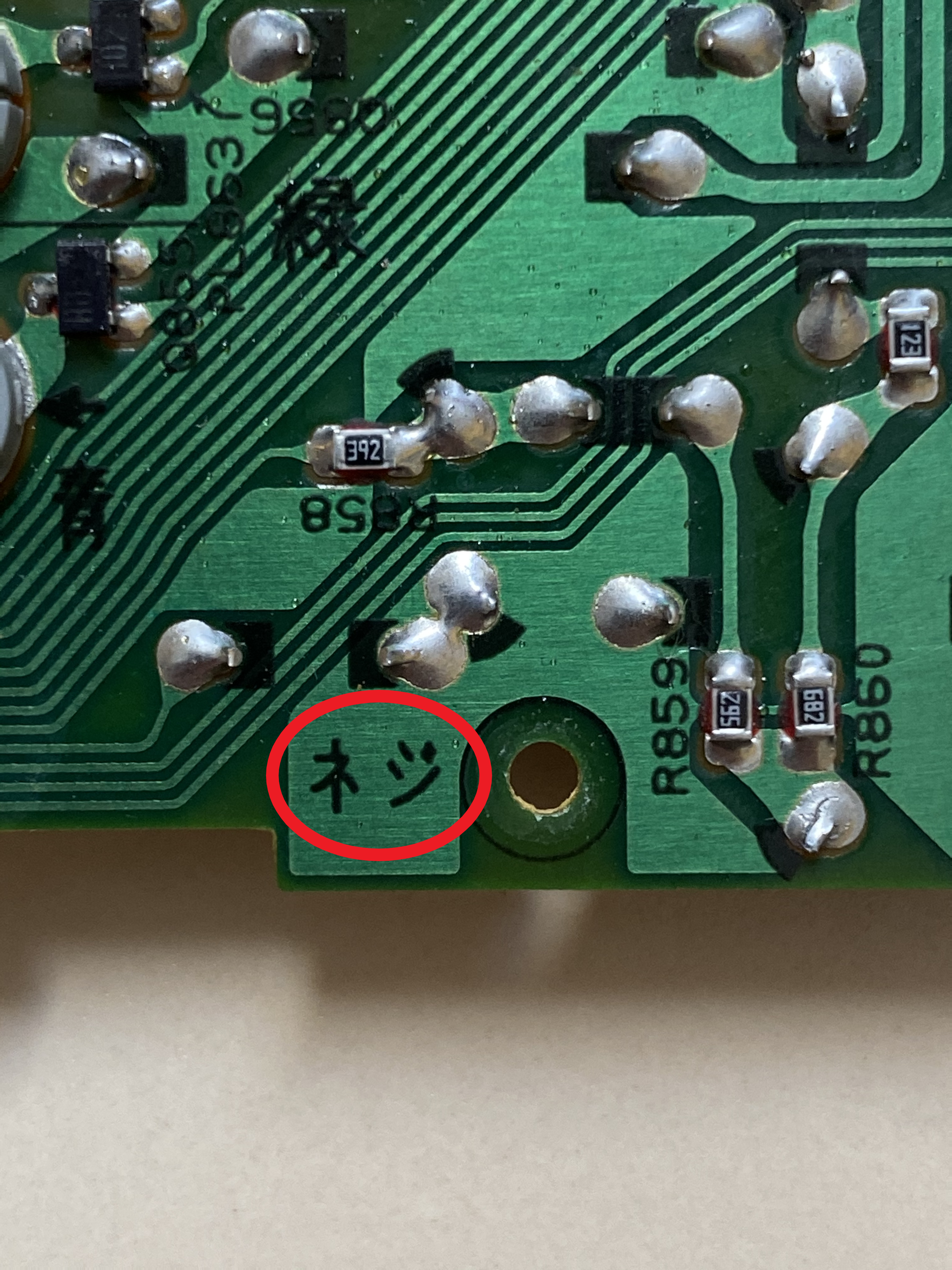
ネジ (neji) literally means “screw,” so I’m sure you can guess what goes there. 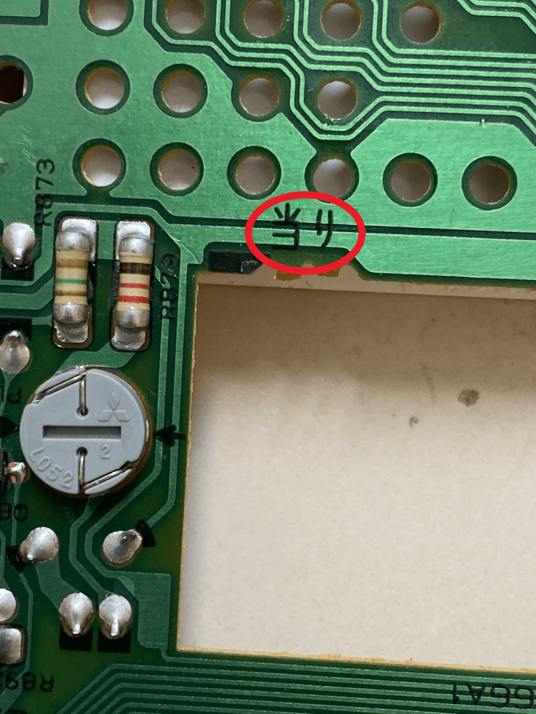
当り (atari) has quite a few different meanings, such as “hit, success, guess,” and “touch/sensation.” In this context, my best guess is that it means “contact point” because anywhere this was marked was a spot where plastic tabs would click into place (maybe the feeling of it clicking in would indicate “success”? I’m not sure…). 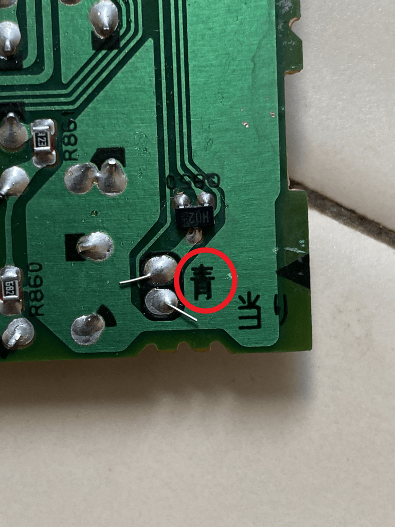
青 (ao) can mean “blue” or “green” (I know, confusing. I’ve heard it said that the green indicated by 青 is more of a blue-green). I’m assuming that this is indicating either particular electrical paths on the board or where there are traces (the lines in the PC board which are electrical paths made of copper). 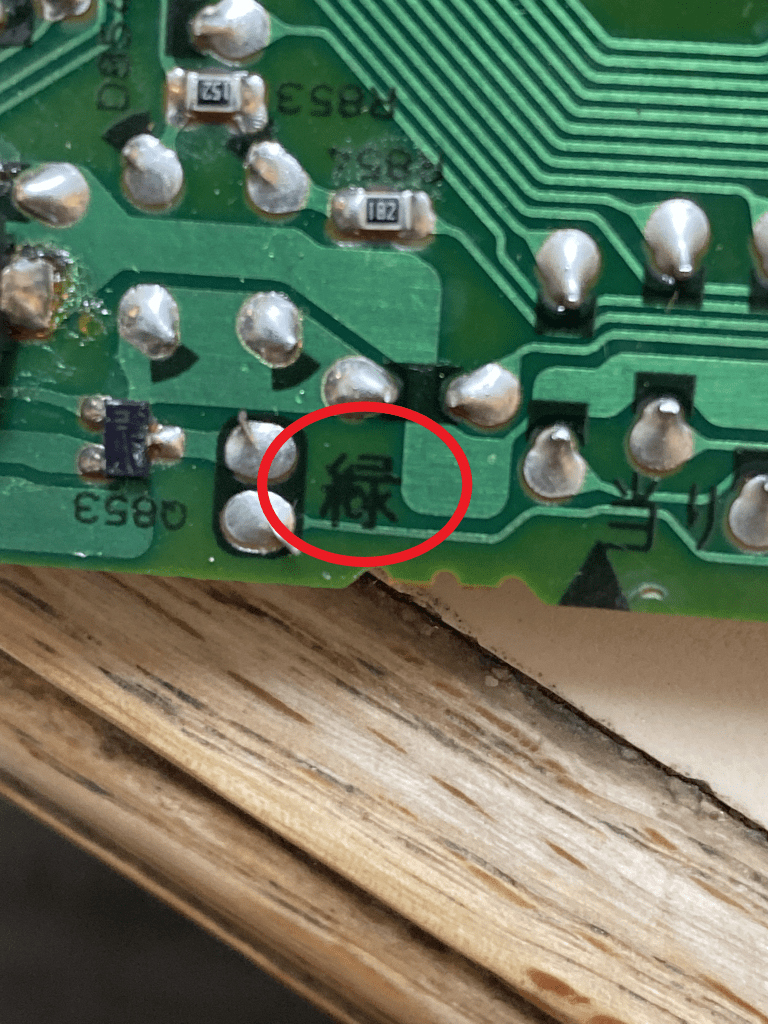
This is 緑 (midori) which means “green” (yup, another green). However, it can also mean “greenery.” So, I’m not sure if it is pointing out a different pathway from “ao,” or if it is used figuratively to mean something akin to “greenspace” (as if the parts of the board with no traces are like parks or something; maybe I’m getting too symbolic…). 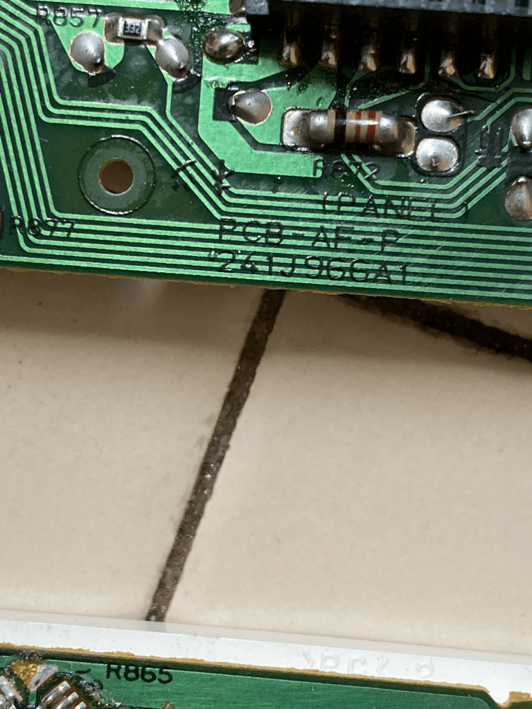
This is just the part number for the board itself.
Again with the help of my father, the soldering went quite smoothly. With the encoder back in, it was time to put everything back together and try it out.
I run out to the car and plug everything in. The lights come on, the radio starts, I put in a tape, and… nothing. The player won’t accept the tape. It’s as if it won’t even recognize it. I press the tape button. Same result.
Bewildered, I take it back into the house and check all of the connections. After multiple attempts, I realized that there were two connectors on the board which had fatigued. One had lost a few connections and even pulled a trace out of the board.
We soldered these back in place and then used a small piece of wire to repair the trace. Double- and triple-checking, everything seemed good to go. I went back out and plugged it in. This time, the radio wanted the security code, but I could not get it to respond at all. Oddly enough, the only thing that worked was the on/off button on the encoder; the volume control was also perfectly smooth. So, I had solved that problem and created an entirely new one.
Knowing When to Close Up Shop
The amount of time I spent on this project was quite significant, and eventually I had to call it quits and get a new radio. I settled on a Kenwood stereo which has Bluetooth built in.
I was pretty discouraged after what I felt was a tremendous failure after such hard work. I couldn’t think of anything else that would fix the radio. Focusing on the failure only caused me to be more crestfallen.
Later that evening, I was speaking with my fiancée and relayed my woes to her. Her reply was both wise and consoling: “Bernie, how many times do you think some of the most successful people have failed? Countless. And yet it was better to have tried than not at all. Did you learn from it?”
I reflected back. Yeah, I guess I had, hadn’t I? I learned about how both CD and tape players work. I faced the fear of ruining an encoder which I felt could not be replaced and successful repaired it. The inner workings of encoders became less mysterious to me. I was able to learn the best practices for removing solder from a circuit board and replacing the components without accidentally soldering it to unrelated parts (which would cause an electrical short). Broken traces were not as scary as I had once believed.
Although I had not been successful in fixing the radio, the value of what I learned outweighs the time I spent. The radio is still in my possession, resting in the basement. Perhaps at some point again I’ll get adventurous and try my hand at restoring it — just for fun.
Categories
